

Thanks to: Hquick, s10mods, stroker97k1500
Feb. 17, 2011
Please read the disclaimer page
Please visit our FORUM. All discussion, questions and comments about this article are welcome.
Swapping a 12200411 PCM into an early OBDII GMT400 truck is not difficult. It is mostly just simply moving pins from the blackbox connector to the 411 PCM connector, however there are a few splices that need to be made. Therefore, being able to crimp-solder-seal is a skill you'll want to have.
The first thing you'll want to do when considering the 411 swap is to obtain the correct wiring file for your application. To do this you'll want to send a PM to Lextech with your truck's year, model, engine, and transmission, along with your e-mail address. He will e-mail you the proper wiring spreadsheet. Once you have it, look over it and get familiar with how it works. The spreadsheet is organized by the wiring pinouts with the blackbox PCM pin # and the corresponding 411 PCM pin #.
Please take extra time to fully read this article, and study the pinout spreadsheet BEFORE you start the swap. 99% of the problems that have been reported from the 411 swap have been because of incorrectly pinning the wires at the PCM. It is absolutely vital that you take your time, read everything thoroughly, and only pin one wire at a time verifying the position, and color of each wire before it is removed, and verifying that it is being placed in the correct position on the 411 connector.
Things you'll need for the swap:
1) 12200411 PCM
2) both 80 pin 411 PCM connectors
3) 2 red retainers and 2 blue retainers
4) a few extra PCM pins (maybe 5-6 extra depending on what truck you're working on), if you get your 411 pcm from a junkyard, see if you can get the PCM, connectors/retainers, and a foot or so of the harness wiring. If you don't get the extra harness, you can get PCM pins from places like eficonnection, I would recommend getting 10 or more incase you drop some or mis-crimp them, or something. They're pretty cheap, I like to err on the side of caution.
5) A tuning software like EFILive, or some other way of tuning the 411 PCM to work correctly.
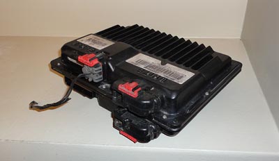
This is the 411 PCM:
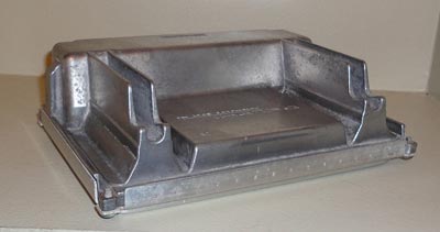
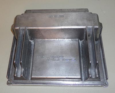
They came in many different 2000+ vehicles, however its most notably in the 2001-2002 trucks, Fbodies, Corvettes, Express vans, etc. Any of these 411 PCMs will work with the proper tune flashed into them. however EVERY 411 PCM will need a tune flashed into it to work, so no one specific 411 PCM is better to use than another. The 411 PCM will have a sticker located on the bottom of it which gives some information about the PCM so you can make sure it is a 411. the sticker will look like this:
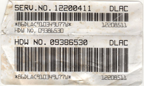
What you'll want to look for is the Service number (SERV.NO.) 12200411.
These are the parts for the 411 PCM 80 pin connectors
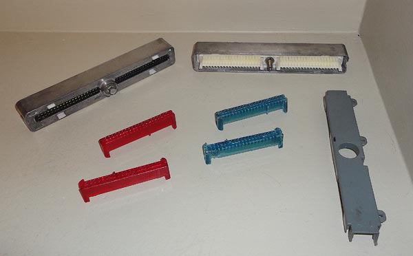
Up at the top you can see the 2 80 pin connectors, below that is the 4 retainers (2 red, 2 blue). and on the far right is a cover which goes over the wires that come out of the connector. This cover is simply cosmetic and is not required to get. it sits on the back of the connector like this:
Personally, I find these covers really annoying, and I prefer to not even have them.
Before you actually start the physical swap you may want to address the tuning issues about this swap if you do not have your own tuning suite, as you will need the PCM flashed with the correct tune before this swap will work. If you plan on tuning the PCM yourself, you can do so after installing the PCM, but before actually starting the vehicle. If you're having someone do the tuning for you, you may want to consider having them flash the tune in before you actually install the PCM (i.e. mail order tuners). The tuning section of this swap is detailed towards the end of this page.
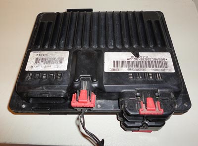
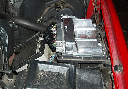
Now lets look at the actual swap. The blackbox PCM looks like this (this PCM is from a '96, if you have a late 97 or newer PCM your blackbox PCM may only have 4 connectors instead of the 5 like this one):
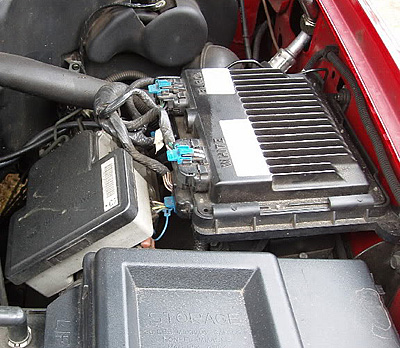
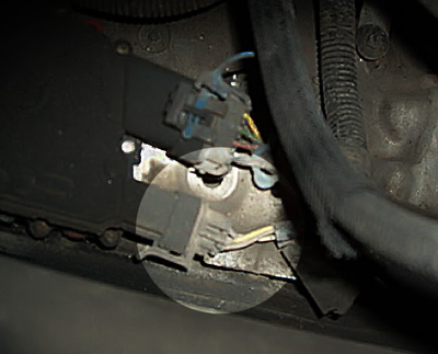
and its located on the drivers side of the engine compartment in the middle of the fender wall (this pic is from a RHD vehicle, yours may be slightly different):
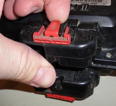
Simply unplug the blackbox PCM by removing the "locking" tabs:
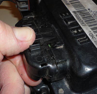
Then unplug the connectors:
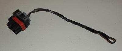
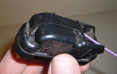
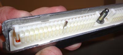
This is about what the connector will look like, however it will have many more wires coming from it, for this write up I only put in one wire to demonstrate with.
There will be 4 of these connectors on the blackbox, go ahead and unplug them all and remove the blackbox PCM from the vehicle. If you have a 96 or early 97 PCM, you will also have a 5th connector, if you do have this 5th connector, what you'll want to do is un-loom about 8-10" of the wiring harness. There are 2 wires connected to the 5th connector, however all it is, is a jumper wire, so once you unravel back enough, you can just remove that connector and wire alltogether.
Okay, now you should have all 4 blackbox connectors there, and you should also have your 2 80 pin connectors there as well. First you'll want to label which 80 pin connector is which, so that while you are wiring you do not get them mixed up. I'd suggest putting a piece of tape on them and labeling them C1 (blue) and C2 (red). Okay, at this point you'll want to remove the red and blue pin retainers from both 80 pin connectors if they aren't already. To do this you'll need something small and thin like a very small jewelers screwdriver or something similar. There is a small opening on either side of the retainers, use the small screwdriver to press in on the tab in those holes to unlatch the retainer, once both sides have been released, simply pull the retainer off.
So you've got both 80 pin connectors ready, and labeled with the retainers removed. Now consult your wiring spreadsheet, and grab the blackbox connector which corresponds to C1 (retainer color may vary depending on the vehicle you are working with. the spreadsheet will explain which colors correspond to which connector (C1, C2, C3, and C4) on the blackbox). You will only want to work with ONE connector at a time. So grab the blackbox connector C1 and remove the retainer in the same manner as the 411 retainers. once you have the retainer off, go ahead and open up the back of the blackbox connector.
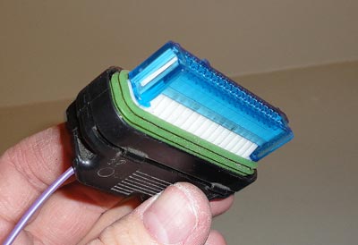
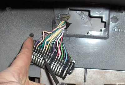
There are 2 halves to the back of the blackbox connectors, you can see the little latches in the picture above. You should be able to just pull them apart, maybe with a little help using a small flathead screwdriver. Then the 2 halves just swing out of the way like this:
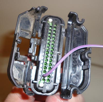
Again, you'll have a lot more wires coming out. Now what you'll want to do is simply follow the spreadsheet. Removing one wire at a time from the blackbox connector, and placing in its correct spot in the 411 connectors. ONLY DO ONE WIRE AT A TIME! if you try to remove a bunch of wires at a time you are going to make an error and have to spend lots of time and energy trying to trace down the problem afterwards. Save yourself the headaches, and problems and only pull and place one wire at a time, it would also be wise to verify the wire color, and make any note of wire color discrepancy vs the spreadsheet incase you need to investigate something in the future. The spreadsheet has been used many times and is well refined. but in the early OBDII years, there were a few little differences in simple things like wire colors that we are not able to keep track of. The pinouts are all correct, but if you're like me, you'll want to double check stuff as you're doing it to prevent any issues.
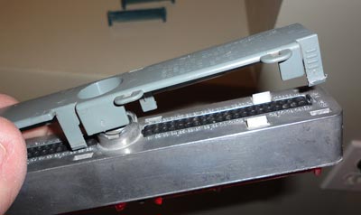
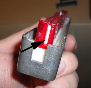
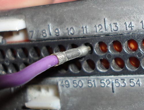
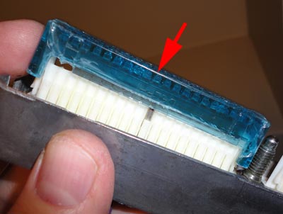
Both connectors will be numbered which is referred to on the spreadsheet, for example, in the following image, the purple/white wire is in pin #2. The spreadsheet will tell you where the pin/wire is coming from, and where it is going to according to the connector number, and pin number. We'll remove this wire from this connector, pin #2, and insert it into the 411 connector pin #11 for this demonstration.
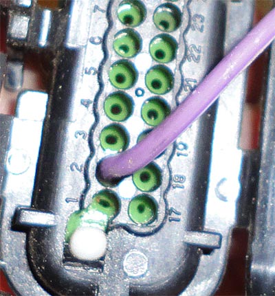
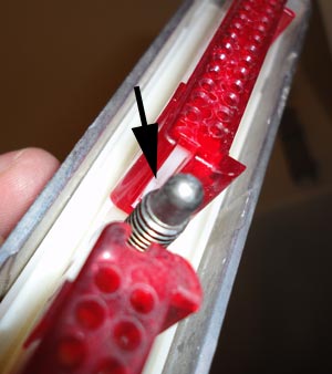
To remove the pins is fairly easy, there are 2 little hooks that hold the PCM pin in place. There is a little tab the protrudes up on the outside of the connector, this tab needs to be gently pulled away from the PCM pin, and the pin itself needs to be pushed away from the connector body slightly, and down. Once the pin has cleared the little barbs that hold it up, you can simply pull the wire and pin out the back of the connector.
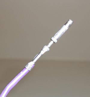
This is what the pin will look like once you have it removed:
Now that you have it removed, you are ready to insert it into the 411 connector. So locate the proper 411 80 pin connector, and locate the correct pin # on that connector. For this demonstration we will install this pin into pin#11. here is part of the back of one of the 411 connectors, you can see all the pin #'s, they simply go in order, so you can see 1, 2, 3, 4, then there are a few numbers missing due to the hole in the back, pin #5 and 6 are there, then the counting continues, 7, 8, 9, etc...
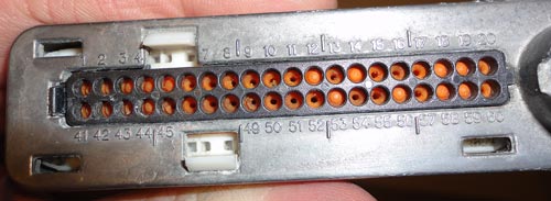
We need to find pin #11 which is on the top row, in the middle of the above image. So you do is take the PCM pin you just removed, and insert it into the slot for pin #11
Go ahead and push it in all the way until the pin clicks into place. This image shows the pin all the way inserted and complete
Now go through and swap over all the pins and add the few splices like are detailed in the wiring spreadsheet.
If you have an automatic transmission, there are a few more that need to be added as well. The spreadsheet will refer to 'trans harness' which is on the PARK/NEUTRAL switch on the right (drivers) side of the transmission, and looks like this:
If you don't want to splice into the wires at the trans, you have another option, you can also splice into the gauge cluster harness and send those signals over to the PCM. If you want to do it this way, you'll need to remove your gauge cluster, then remove the cluster connector, and splice into the following pins for the trans signals:
Transmission Range Switch Signal A (blk/wht) = Pin 9
Transmission Range Switch Signal C (grey) = Pin 10
Transmission Range Switch Signal B (yellow) = Pin 11
Transmission Range Switch Signal P (white) = Pin 12
However you decide to do it, you'll be splicing into these wires and running an additional signal to the PCM so that the 411 will be able to see what gear is selected.
There are a few other splices that will need to be done up near the PCM, but which ones are needed will vary depending on your application, please refer to the wiring spreadsheet for that information. And for all the splices, I would recommend doing a quality crimp-solder-seal to get the best conduction and longevity of the splice. If you do not know how to properly splice, please ask, we will help, if there is enough questions about it, perhaps we can do a separate write up on proper splicing technique.
After you have all the pins moved from all the blackbox connectors, and you have finished all the splicing, you are ready to put the red and blue retainers back on the 411 connectors, simply align them and push down until they click into place. make sure the blue retainers go on the connector that you labeled as C1(blue), and the red retainers on C2(red).
Now that the connectors are completely pinned and all ready you can plug them into the 411 PCM, there in only one way they can be plugged into the PCM with the red and blue retainers installed, but the C1 blue connector is on top, C2 red connector is on the bottom. The little bolts that hold the connectors in are 7mm, do not over tighten them, there are actual torque values, but I always just snug them up a little.
The PCM should fit in the bracket that held the blackbox PCM, however the wire bracketry that slipped over the blackbox PCM to hold it in place does not work on the 411. you may want to fab something up to hold the PCM in there. But that likely isn't needed. My 411 PCM has been installed and just sitting in the blackbox bracket without a problem for years, so that is really up to you. And other than tuning, which is explained below, the PCM is installed.
Not too difficult.
TUNING
In order for the 411 PCM to work, it needs to be flashed with a proper tune. To do this, you either need a tuning suite (like EFILive or another program which is compatible with the 411) to do this yourself. Or you can talk to any number of mail order and custom tuners out there who should be able to make the necessary changes for you.
If you are at all interested in tuning your vehicle yourself. I would highly recommend it. There is somewhat of a learning curve, however once you get used to how tuning works, it is not too difficult. But that is a topic for another article.
You need to start with a 2002 Express van base tune. The express van is the key to why this swap works since the 2002 express used both the L31 vortec engine and the 12200411 PCM. So starting with the 2002 Express van L31 tune for your correct transmission, the following items need to be changed.
1) Turn off the VATS (Vehicle anti theft)
2) Disable Alternator codes (aka generator)
3) Depending on your setup you may need to also disable the fuel tank pressure sensor codes, and possibly post cat O2 sensors. Your specific wiring spreadsheet will detail this information as well.
4) You should also program in your correct VIN number. You are able to put any VIN number in these PCMs, so it doesn't matter if your VIN is from before the 411 was in use or not.
The following files are the appropriate 2002 Express Van (OS 12212156) base tune files you can freely download and use. I've altered these tunes as mentioned above, but they are just base tunes, you still need to modify them for your specific setup (i.e. VIN, Injector flow rates, VE tables, Spark tables, gear ratio, EGR/EVAP/AIR/other emissions devices you may or may not have, etc.) they are also all 5.7L base tunes so if you have a 5.0L or something else, you'll have to correct that as well.
All these tuning files are EFILive tuning files, if you have a different tuning suite you will need to find the correct tuning files for your program.
Base Tune 5.7L Manual Transmission
You also may or may not get a P1336 code. This code indicates that you need a crank relearn (CASE) done. However, even if you do not get this code you really should have a crank relearn (CASE) done. What this does is provide data to the PCM so that it can identify the position of the crank for alot of things like misfires and such. A tuning software such as EFILive can perform this, otherwise you'll need to find a shop or dealer with somthing like a TechII which can perform this test as well. The CASE relearn shouldn't take more than a few minutes however you get it completed.
Troubleshooting
If you've completed the swap and are having trouble, there are a few common things you'll want to look at first.
If your truck does not start AT ALL, meaning you don't get much other than the starter when you turn the key, then its likely that the tune you are trying to run doesn't have the VATS turned off. you'll need to get the PCM tuned correctly as mentioned above.
If you have a 1996-1997 truck, and it idles very poorly or is unable to stay idling, but smooths out as you raise the RPM. If you unplug the EGR valve and the problem goes away, you haven't correctly wired up the EGR valve, in the 96-97 years, the EGR was controlled differently than later years and an additional wire has to be added to retain EGR functionality. This is explained in the paragraphs at the top of the pinout spreadsheet. Please review the instructions in the spreadsheet.
If you have any other issues that were not present before the swap, the FIRST thing you'll need to do is double check EVERY wire, and verify it against the spreadsheet. Make sure the wire color and position of the wire is 100% correct. If you've already looked over it, check it again, if you're pretty sure that it's correct, check it again. One wire simply placed one position out of place can be the difference between a running truck, and a non-running one. This is where most of the problems reported from the swap come from.
The pinout spreadsheets are correct, they have been tested, and proved accurate many times, by many people all over the world. If you are still having difficulties, or questions, feel free to post up and we will try to help you out.
The original thread where this started is located on the pacific performance engineering forum here
To comment, discuss, or ask questions about this article, please click here to visit our forum.