By: Aloicious
Feb. 13, 2012
Please read the disclaimer page
Please visit our FORUM. All discussion, questions and comments about this article are welcome.
Welcome to part two of our fuel injector series where we will discuss fuel injectors in depth, from their basic function, to advanced topics like injector dynamics and tuning.
In part two we will talk about control of the fuel injector. As we briefly discussed in part one, the injector is supplied with a switched 12V positive voltage, however the injector controller provides a negative ground signal to complete the circuit and turn the injector 'ON', and subsequently remove this negative ground to turn the injector 'OFF'.
Now, fuel injectors, when they are 'ON', they flow at a constant rate. This rate is usually measured in either pounds per hours, cubic centimeters per minute, or grams per second, all these measurements are also rated at a stable and given fuel pressure, the standard pressure for rating injectors is normally 43.5psi, or 3 BAR. However even though that is the standard, sometimes injectors are flow tested at different pressures, but we’ll talk about that later when we discuss choosing the right injector. Now since the injector flows at a constant rate, and can only be either on, or off, at a given time, we need to know how the controller can vary the amount of fuel that is delivered based off the engine's need. The way this is accomplished is with pulse width modulation, and varied duty cycling.
First we’ll talk about pulse widths. Basically, a pulse width is the time period that an injector is switched on, typically measured in milliseconds. The injector will be switched on, and off very frequently, many times per minute. When looking at these pulses on an oscilloscope, the X axis of the scope is time, so measuring the width of a pulse represents the length of time that the injector is pulsed on. A longer pulse will deliver more fuel than a shorter pulse from the same injector, obviously. So the injector controller will vary the pulse widths to deliver a varied amount of fuel for any single pulse.
Now when we start talking about multiple pulse widths over a period of time, we need to talk about duty cycling. The duty cycle is simply the percentage of time that an injector is pulsed on, vs. off. So a higher duty cycle means that the injector is pulsed ‘on’ for a larger percentage of time, regardless of the length of each actual pulse width, and hence delivers more fuel than a lower duty cycle. Pulse widths and duty cycles are interlinked to each other, but at the same time, they are independent of each other as well. Remember that individual ‘on’ periods are the pulse widths, but over a period of time and multiple pulse widths, the percentage of time that the injector is ‘on’ from the collective of the pulse widths is the duty cycle, this is how they are interlinked. Now, normally a higher duty cycle will correlate to longer pulse widths, but that is not always the case, you could have short pulse widths with very short rest periods in between, which could result in a high duty cycle, this is how they can be considered independent as well.
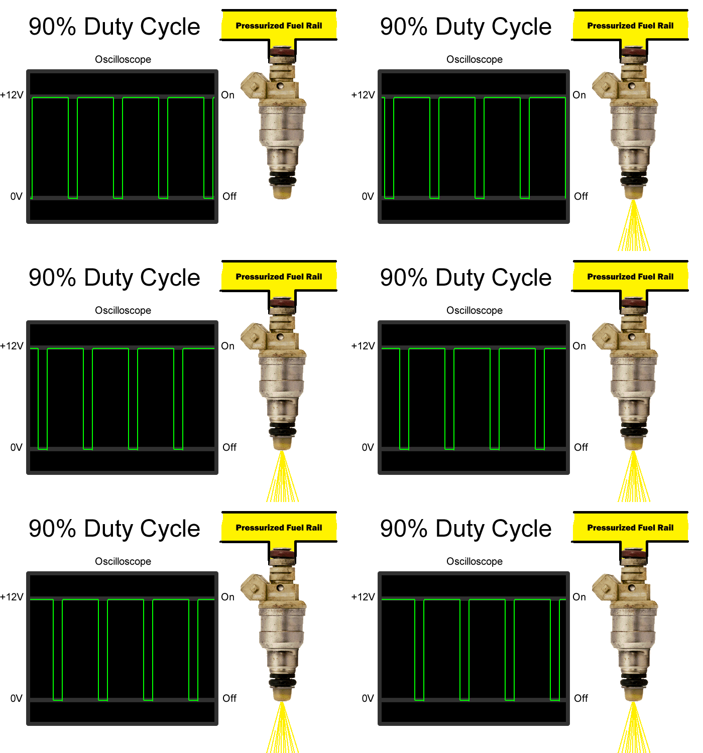
Let’s look at some examples. Now in these example images you will see an example of a simplified oscilloscope. Now, just to clarify, this is a simplified oscilloscope, the waveform that is represented is not what you would normally see when hooking an oscilloscope onto a injector on an engine, the waveform is more like what you would see from a function generator that could drive the injector. Understanding this is not a requirement to understand this article, but rather just to be clear on the simplified readout. This waveform is much easier to understand this portion of the article, in a later section we will discuss real oscilloscope readings and measurements.
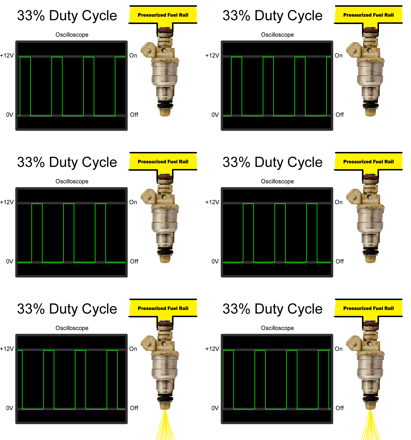
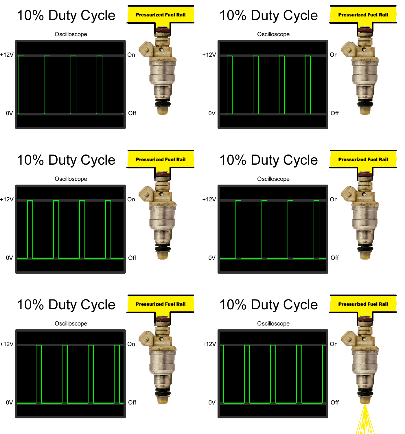
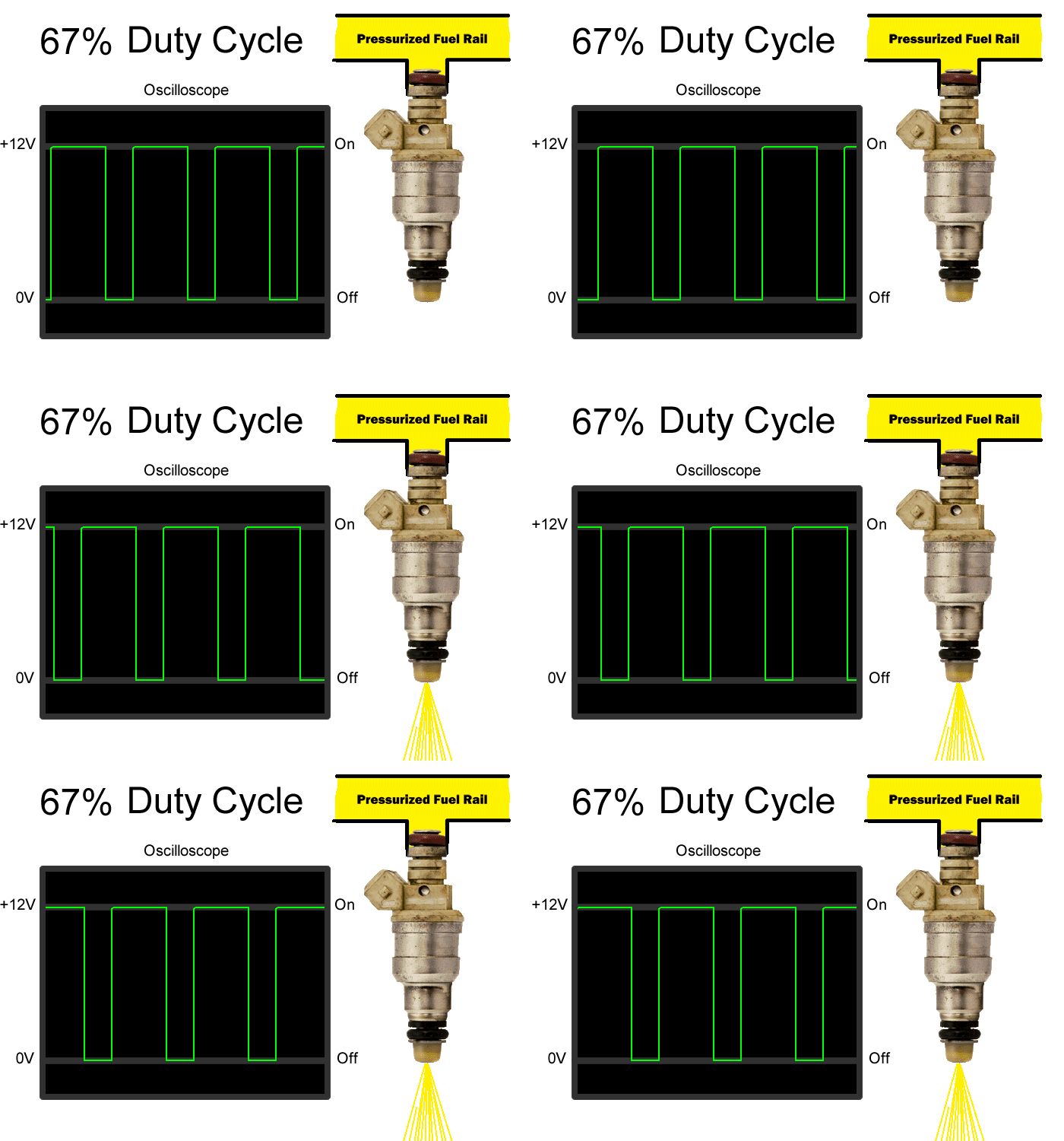
So when we look at these examples, on the oscilloscope, the far left is ‘real time’ as the waveform scrolls left to right. When the green signal line is up at the 12V section, then the injector circuit is complete, and the injector is ‘on’ at these points you will see the example injector on the right of the image spraying fuel, when the green oscilloscope signal line is down at the OV portion of the readout, this is when the injector is ‘off’ and you will see the example injector stop flowing fuel.
The first example we’ll look at is a 50% duty cycle.
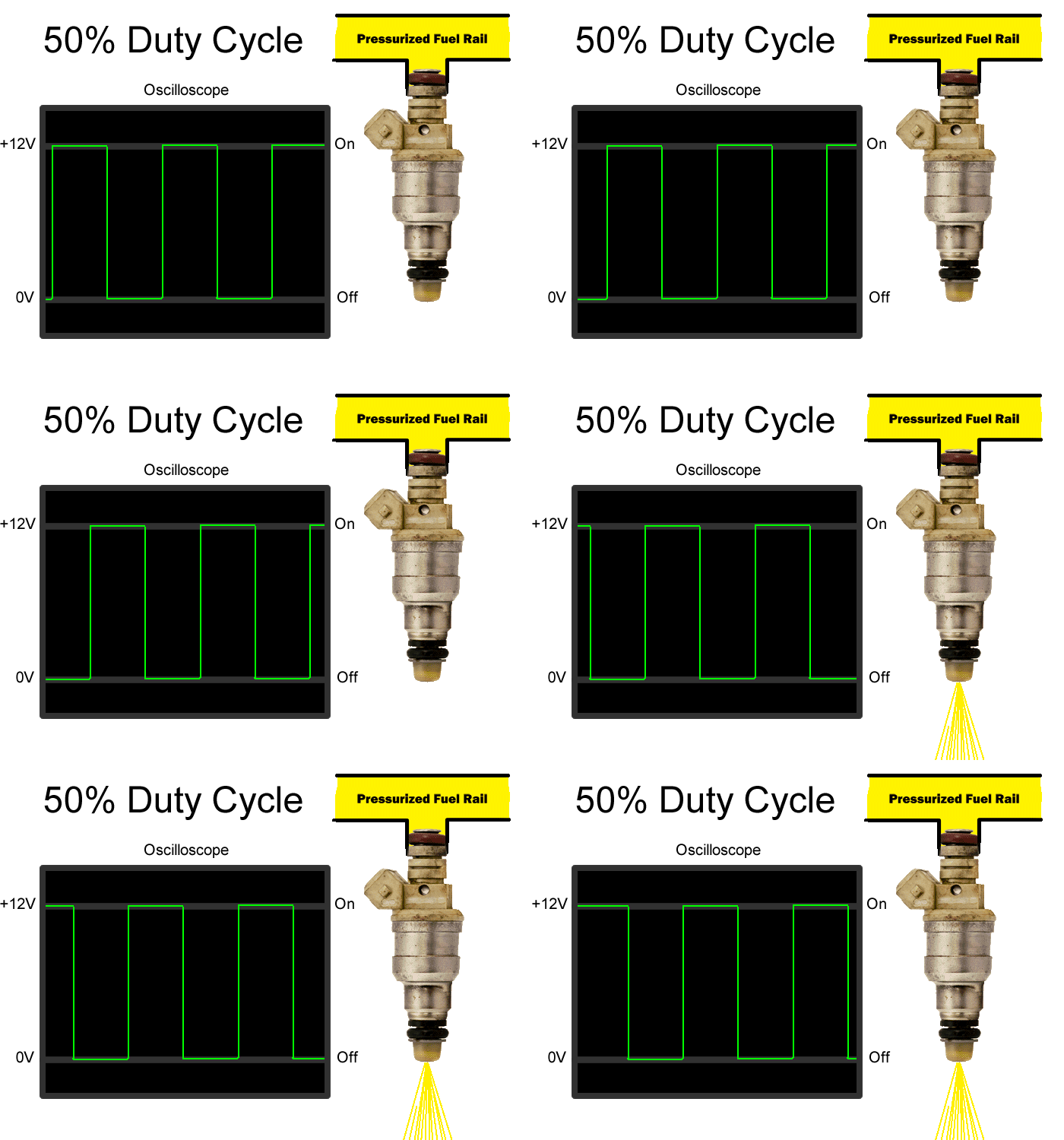
You’ll notice that the injector is commanded to be ‘on’ the same amount of time that it ‘off’ so it is on and flowing fuel 50% of the time. Pretty easy, right? You can see the width of each pulse (the pulse width) and the overall duty cycle.
Now if we dial it back a little bit, to say 33% duty cycle, you’ll see that the injector is firing less and delivering less fuel. You’ll also see, at least in this example, that each pulse width is also shorter.
If we go even further and dial it back to 10% duty cycle, the injector is now delivering much less fuel over the exact same period of time.
We can also go the other way, if we crank up the duty cycle higher to 67%, then you can see that the time the injector is firing is the majority, this will obviously deliver much more fuel.
And in our last example, we’ll jump the duty cycle all the way up to 90%. You can see how much varying the duty cycle, and pulse widths, can deliver a wide range of fuel volume, even though the injector can only flow at a constant rate, and at any point in time, can only be either on or off.
So you might be thinking, what about 100% duty cycle, obviously, this is when the injector is on all the time, without pulses, typically this is called being ‘static’ or ‘static flow’. This is the maximum amount of fuel that an injector can deliver without adjusting external factors like the fuel system pressure. Also, worth noting is that due to injector dynamics, when you choose an injector for your setup, you want to get one that will peak around 80% duty cycle, getting too small of an injector can cause the engine to run lean at heavy loads, which can cause damage, going too big with an injector can also cause problems on the other end of the spectrum. We will discuss this more in detail in a later section of the series though, just realize right now that there are variables that come into play and make the extremes of the duty cycles an important role when selecting an injector setup.
Coming up next is the section on functional injector dynamics. It will be up soon, so stay tuned.
Previous section: Injector Basics
Next section: Injector Dynamics
To comment, discuss, or ask questions about this article, please click here to visit our forum.

